

[BOUNDARY] What is the difference between rigid link and rigid type elastic link ?
When defining a elastic link, under certain conditions Rigid type
Elastic link may be defined. How is it different from defining the link as
Rigid Link
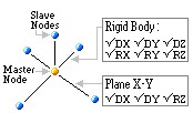
Rigid link constraints are geometric, relative movement of a structure, where degrees of freedom of subordinated nodes called Slave Nodes are constrained by a particular reference node called the Master Node. The relative movements of the master node and slave nodes are
such as if they are interconnected by a three-dimensional rigid body. In this case, relative nodal displacements are kept constant.
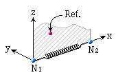
While an Elastic link connects two nodes to act as an element, where the user defines its stiffness.
Rigid Type of Elastic Link and Rigid Link are similar in that both are used to simulate rigid behaviour.
However, the user must be cautious in using them because their internal processes are different in the program
RIGID LINK
ELASTIC LINK
1. Rigid type Elastic Link vs Rigid Link
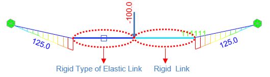
In the case of Rigid Type Elastic Link, the element stiffness is automatically calculated based on the working model, assigning a large stiffness value of magnitude 105~108 times the stiffness of neighbouring elements.
Such exceptionally large stiffness may cause a numerical error because of the relatively large stiffness of the link element.
Therefore, when the model contains an element, that has large stiffness to replicate a rigid action,
it is recommended that a Rigid Link be used rather than a Rigid Type Elastic Link. Rigid Link geometrically constrains
the relative movements between the Master and Slave Nodes without being affected by the large stiffness of other members.
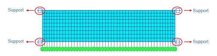
2. Rigid Link + Support

Rigid link should never be assigned with a boundary condition.
Looking at Model 2, the support boundary condition is applied to the Master Node of Rigid Link,
which implies the support condition is also applied to the Slave Node. This should be avoided. While in Model 3,
the support condition is applied to the Slave node. Slave node is constrained by the Master node boundary condition and hence the Slave Node will be ignored.
Model 1 (Rigid Link Elastic Link Support), is the right way to define a boundary
condition.
3. Elastic Link + Support
Elastic Link has not been assigned boundary conditions. In such a case, the links will be considered as beam elements having the equivalent stiffness.
In order to correct this, the ends of the elastic links must be assigned proper boundary conditions or Point Spring Support.
4. Computational Time for Analysis
The figure below shows a process in which a total of 72 (6x12) d.o.f are compressed to 54 d.o.f with in the plane of the diaphragm,
depicting the behavior of a cross girder in a bridge deck.
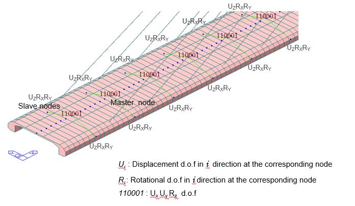
If a degree-of-freedom of a particular slave node is constrained to a master node for the relevant degree-of-freedom,
by using "Rigid Link" relationship, all the attributes (nodal load or nodal mass) including the stiffness
component of the slave node are converted into an equivalent component of the master node.
Giving such geometric constraints reduces the number of degrees of freedom which can significantly reduce the computational time for analysis.
For instance, consider the cable stayed bridge in the figure above where ‘Rigid Link’ action is used to depict cross girder diaphragm action.
If this link is analyzed with the diaphragms modeled as Rigid type Elastic link, the number of d.o.f will increase substantially.
Each node represents 3 additional degrees of freedom. Hence in a model with large number of nodes in an analysis can result in excessive program execution time,
or it may even surpass the program capacity. It is therefore recommended that the number of degrees of
freedom be minimized as long as the accuracy of the results is not compromised.
Elastic link may be defined. How is it different from defining the link as
Rigid Link
Rigid link constraints are geometric, relative movement of a structure, where degrees of freedom of subordinated nodes called Slave Nodes are constrained by a particular reference node called the Master Node. The relative movements of the master node and slave nodes are
such as if they are interconnected by a three-dimensional rigid body. In this case, relative nodal displacements are kept constant.
While an Elastic link connects two nodes to act as an element, where the user defines its stiffness.
Rigid Type of Elastic Link and Rigid Link are similar in that both are used to simulate rigid behaviour.
However, the user must be cautious in using them because their internal processes are different in the program
RIGID LINK
ELASTIC LINK
1. Rigid type Elastic Link vs Rigid Link
In the case of Rigid Type Elastic Link, the element stiffness is automatically calculated based on the working model, assigning a large stiffness value of magnitude 105~108 times the stiffness of neighbouring elements.
Such exceptionally large stiffness may cause a numerical error because of the relatively large stiffness of the link element.
Therefore, when the model contains an element, that has large stiffness to replicate a rigid action,
it is recommended that a Rigid Link be used rather than a Rigid Type Elastic Link. Rigid Link geometrically constrains
the relative movements between the Master and Slave Nodes without being affected by the large stiffness of other members.
2. Rigid Link + Support
Rigid link should never be assigned with a boundary condition.
Looking at Model 2, the support boundary condition is applied to the Master Node of Rigid Link,
which implies the support condition is also applied to the Slave Node. This should be avoided. While in Model 3,
the support condition is applied to the Slave node. Slave node is constrained by the Master node boundary condition and hence the Slave Node will be ignored.
Model 1 (Rigid Link Elastic Link Support), is the right way to define a boundary
condition.
3. Elastic Link + Support
Elastic Link has not been assigned boundary conditions. In such a case, the links will be considered as beam elements having the equivalent stiffness.
In order to correct this, the ends of the elastic links must be assigned proper boundary conditions or Point Spring Support.
4. Computational Time for Analysis
The figure below shows a process in which a total of 72 (6x12) d.o.f are compressed to 54 d.o.f with in the plane of the diaphragm,
depicting the behavior of a cross girder in a bridge deck.
If a degree-of-freedom of a particular slave node is constrained to a master node for the relevant degree-of-freedom,
by using "Rigid Link" relationship, all the attributes (nodal load or nodal mass) including the stiffness
component of the slave node are converted into an equivalent component of the master node.
Giving such geometric constraints reduces the number of degrees of freedom which can significantly reduce the computational time for analysis.
For instance, consider the cable stayed bridge in the figure above where ‘Rigid Link’ action is used to depict cross girder diaphragm action.
If this link is analyzed with the diaphragms modeled as Rigid type Elastic link, the number of d.o.f will increase substantially.
Each node represents 3 additional degrees of freedom. Hence in a model with large number of nodes in an analysis can result in excessive program execution time,
or it may even surpass the program capacity. It is therefore recommended that the number of degrees of
freedom be minimized as long as the accuracy of the results is not compromised.
2016_FAQ_Vol.1_image (1)[1].jpg

2016_FAQ_Vol.1_image (1)[1].jpg
2016_FAQ_Vol.1_image (1)[2].jpg

2016_FAQ_Vol.1_image (1)[2].jpg
2016_FAQ_Vol.1_image (1)[3].jpg

2016_FAQ_Vol.1_image (1)[3].jpg
2016_FAQ_Vol.1_image (1)[4].jpg

2016_FAQ_Vol.1_image (1)[4].jpg
2016_FAQ_Vol.1_image (81).jpg

2016_FAQ_Vol.1_image (81).jpg
2016_FAQ_Vol.1_image (82).jpg

2016_FAQ_Vol.1_image (82).jpg
Vol.1_37_What is the difference between rigid link and rigid type elastic link.pdf
Vol.1_37_What is the difference between rigid link and rigid type elastic link.pdf
 Get help for this page
 Jitbit HelpDesk