

Rigid Link DOF Error
Question:
Dear Sir,
Take a look at the model attached.
When I ran it, i got an error message:
Duplicated degrees-of-freedom component exist at the Rigid Link (Diaphragm) of Node no. 3565.
Can you tell me what is wrong with the model?
thanks
Answer:
Thanks for writing to us.
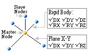
Rigid Link is to Constrain certain degrees-of-freedom of Slave Nodes to a Master Node.
Slave node cannot have additional boundary conditions or other constraints.
kindly go through this article https://midassupport.jitbit.com/helpdesk/KB/View/5264129-boundary-----what-is-the-difference-between-rigid-link-and-rigid-type-elastic-link-
Also we can use beam-end releases option to manipulate DOF. http://manual.midasuser.com/EN_Common/Civil/865/Start/04_Model/06_Boundaries/Beam_End_Release.htm
kindly reply back if you have any further issues.
Regards,
------------------------------------------------------------------------------------------------------------------------------------
Hi,Suman,
Thanks for your reply.
Following your reply "Slave node cannot have additional boundary conditions or other constraints.", I had another look at my model: Node 3565 is a master to Node 3410 where the slave Node 3410 has NO additional boundary conditions or constraints.
At the same time, Node 3565 is slaved to Node 3562 where the slave Node 3565 has NO additional boundary conditions or constraints.
Therefore the mode should be ok per your reply. And yet the analysis does not run, giving me the message "[Error]Duplicated degrees-of-freedom component exist at the Rigid Link (Diaphragm) of Node no. 3565."
Plus I have similar scenarios at other nodes (a master node is slaved to another node) but the there is no error message on these nodes.
I got really confused.
--------------------------------------------------------------------------------------------------------------------------------------------------------
Hi,
I have made a simple test model to explain the issue. PFA the model.
[Error occurs] - We cannot make a slave node of one rigid link, as a Master node of another rigid link.

To resolve this issue we can utilize features below:
1)Rigid elastic link, for full rigid-DOF between two nodes.

2) Rigid link without/ with different releases

3) Beam-End Release

kindly go through our online help manual for this feature. http://manual.midasuser.com/EN_Common/Civil/865/Start/04_Model/06_Boundaries/Beam_End_Release.htm

I think in your case, we can use the "Rigid link" in combination with beam-end release to correctly transfer the forces with releases as required.
Hope this helps!
Regards,
PFA the test model.
--------------------------------------------------------------------------------------------------------------------------------------------------------
Hi techsupport,
If as you said " We cannot make a slave node of one rigid link, as a Master node of another rigid link.", I have similar scenarios at other nodes (other than Node 3565) where a master node is slaved to another node, but the there is no error message on these nodes.
can you explain that to me?
PS: Technically by the pure definition of rigid link, I don't understand why a slave node of one rigid link cannot be made as a Master node of another rigid link.
thanks
--------------------------------------------------------------------------------------------------------------------------------------------------------
Hi,
The program will also give an error at Node 3565 Rigid link also. Errors will pop up for this Rigid links one by one.
When defining a elastic link, under certain conditions Rigid type
Elastic link may be defined. How is it different from defining the link as
Rigid Link
Rigid link constraints geometric, relative movement of a structure, where degrees of freedom of subordinated nodes called Slave Nodes
are constraint by a particular reference node called Master Node. The relative movements of the master node and slave nodes are
such as if they are interconnected by a three dimensional rigid body. In this case, relative nodal displacements are kept constant.
While an Elastic link connects two nodes to act as an element, where the user defines its stiffness.
Rigid Type of Elastic Link and Rigid Link are similar in that both are used to simulate rigid behavior.
However, the user must be cautious in using them because their internal processes are different in the program
RIGID LINK
ELASTIC LINK
1. Rigid type Elastic Link vs Rigid Link
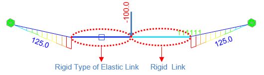
In case of Rigid Type Elastic Link , the element stiffness is automatically calculated based on the working model,
assigning a large stiffness value of magnitude 105~108 times the stiffness of neighboring elements.
Such exceptionally large stiffness may cause a numerical error because of the relatively large stiffness of the link element.
Therefore, when the model contains an element, which has large stiffness to replicate a rigid action,
it is recommended that Rigid Link be used rather than Rigid Type Elastic Link. Rigid Link geometrically constrains
the relative movements between the Master and Slave Nodes without being affected by large stiffness of other members.
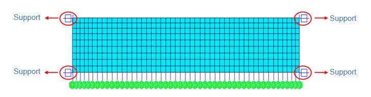
2. Rigid Link + Support

Rigid link should never be assigned with a boundary condition.
Looking at Model 2, the support boundary condition is applied to the Master Node of Rigid Link,
which implies the support condition is also applied to the Slave Node. This should be avoided. While in Model 3,
the support condition is applied to the Slave node. Slave node is constrained by the Master node boundary condition and hence the Slave Node will be ignored.
Model 1 (Rigid Link Elastic Link Support), is the right way to define a boundary
condition.
3. Elastic Link + Support
Elastic Link has not been assigned boundary conditions. In such a case, the links will be considered as beam elements having the equivalent stiffness.
In order to correct this, the ends of the elastic links must be assigned proper boundary conditions or Point Spring Support.
4. Computational Time for Analysis
The figure below shows a process in which a total of 72 (6x12) d.o.f are compressed to 54 d.o.f with in the plane of the diaphragm,
depicting the behavior of a cross girder in a bridge deck.
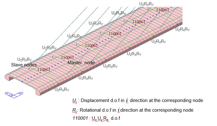
If a degree-of-freedom of a particular slave node is constrained to a master node for the relevant degree-of-freedom,
by using "Rigid Link" relationship, all the attributes (nodal load or nodal mass) including the stiffness
component of the slave node are converted into an equivalent component of the master node.
Giving such geometric constraints reduces the number of degrees of freedom which can significantly reduce the computational time for analysis.
For instance, consider the cable stayed bridge in the figure above where ‘Rigid Link’ action is used to depict cross girder diaphragm action.
If this link is analyzed with the diaphragms modeled as Rigid type Elastic link, the number of d.o.f will increase substantially.
Each node represents 3 additional degrees of freedom. Hence in a model with large number of nodes in an analysis can result in excessive program execution time,
or it may even surpass the program capacity. It is therefore recommended that the number of degrees of
freedom be minimized as long as the accuracy of the results is not compromised.
------------------------------------------------------------------------------------------------------------------------------------------------------------------------------------------
Question: Technically by the pure definition of rigid link, I don't understand why a slave node of one rigid link cannot be made as a Master node of another rigid link.
As slave nodes have geometric constraints linked to master node, they cannot be superimposed with another constraint (like boundary conditions, supports, rigid links etc).
If we are superimposing slave node with a master node of another rigid link, then equilibrium equations established will not converge. At one slave node, two rigid link geometric constrain equations would be improper.
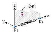
We can solve this by making one master node to connect different slave nodes. See the below figure.

Also, PFA the Rigid Link feature detailed explanation document.
Hope this helps!
Thanks & Regards,
Files:
2016_FAQ_Vol.1_image (1)[1].jpg
2016_FAQ_Vol.1_image (1)[2].jpg
2016_FAQ_Vol.1_image (1)[3].jpg
2016_FAQ_Vol.1_image (1)[4].jpg
2016_FAQ_Vol.1_image (81).jpg
2016_FAQ_Vol.1_image (82).jpg
Vol.1_37_What is the difference between rigid link and rigid type elastic link.pdf
Dear Sir,
Take a look at the model attached.
When I ran it, i got an error message:
Duplicated degrees-of-freedom component exist at the Rigid Link (Diaphragm) of Node no. 3565.
Can you tell me what is wrong with the model?
thanks
Answer:
Thanks for writing to us.
Rigid Link is to Constrain certain degrees-of-freedom of Slave Nodes to a Master Node.
Slave node cannot have additional boundary conditions or other constraints.
kindly go through this article https://midassupport.jitbit.com/helpdesk/KB/View/5264129-boundary-----what-is-the-difference-between-rigid-link-and-rigid-type-elastic-link-
Also we can use beam-end releases option to manipulate DOF. http://manual.midasuser.com/EN_Common/Civil/865/Start/04_Model/06_Boundaries/Beam_End_Release.htm
kindly reply back if you have any further issues.
Regards,
------------------------------------------------------------------------------------------------------------------------------------
Hi,Suman,
Thanks for your reply.
Following your reply "Slave node cannot have additional boundary conditions or other constraints.", I had another look at my model: Node 3565 is a master to Node 3410 where the slave Node 3410 has NO additional boundary conditions or constraints.
At the same time, Node 3565 is slaved to Node 3562 where the slave Node 3565 has NO additional boundary conditions or constraints.
Therefore the mode should be ok per your reply. And yet the analysis does not run, giving me the message "[Error]Duplicated degrees-of-freedom component exist at the Rigid Link (Diaphragm) of Node no. 3565."
Plus I have similar scenarios at other nodes (a master node is slaved to another node) but the there is no error message on these nodes.
I got really confused.
--------------------------------------------------------------------------------------------------------------------------------------------------------
Hi,
I have made a simple test model to explain the issue. PFA the model.
[Error occurs] - We cannot make a slave node of one rigid link, as a Master node of another rigid link.
To resolve this issue we can utilize features below:
1)Rigid elastic link, for full rigid-DOF between two nodes.
2) Rigid link without/ with different releases
3) Beam-End Release
kindly go through our online help manual for this feature. http://manual.midasuser.com/EN_Common/Civil/865/Start/04_Model/06_Boundaries/Beam_End_Release.htm
I think in your case, we can use the "Rigid link" in combination with beam-end release to correctly transfer the forces with releases as required.
Hope this helps!
Regards,
PFA the test model.
--------------------------------------------------------------------------------------------------------------------------------------------------------
Hi techsupport,
If as you said " We cannot make a slave node of one rigid link, as a Master node of another rigid link.", I have similar scenarios at other nodes (other than Node 3565) where a master node is slaved to another node, but the there is no error message on these nodes.
can you explain that to me?
PS: Technically by the pure definition of rigid link, I don't understand why a slave node of one rigid link cannot be made as a Master node of another rigid link.
thanks
--------------------------------------------------------------------------------------------------------------------------------------------------------
Hi,
The program will also give an error at Node 3565 Rigid link also. Errors will pop up for this Rigid links one by one.
When defining a elastic link, under certain conditions Rigid type
Elastic link may be defined. How is it different from defining the link as
Rigid Link
Rigid link constraints geometric, relative movement of a structure, where degrees of freedom of subordinated nodes called Slave Nodes
are constraint by a particular reference node called Master Node. The relative movements of the master node and slave nodes are
such as if they are interconnected by a three dimensional rigid body. In this case, relative nodal displacements are kept constant.
While an Elastic link connects two nodes to act as an element, where the user defines its stiffness.
Rigid Type of Elastic Link and Rigid Link are similar in that both are used to simulate rigid behavior.
However, the user must be cautious in using them because their internal processes are different in the program
RIGID LINK
ELASTIC LINK
1. Rigid type Elastic Link vs Rigid Link
In case of Rigid Type Elastic Link , the element stiffness is automatically calculated based on the working model,
assigning a large stiffness value of magnitude 105~108 times the stiffness of neighboring elements.
Such exceptionally large stiffness may cause a numerical error because of the relatively large stiffness of the link element.
Therefore, when the model contains an element, which has large stiffness to replicate a rigid action,
it is recommended that Rigid Link be used rather than Rigid Type Elastic Link. Rigid Link geometrically constrains
the relative movements between the Master and Slave Nodes without being affected by large stiffness of other members.
2. Rigid Link + Support
Rigid link should never be assigned with a boundary condition.
Looking at Model 2, the support boundary condition is applied to the Master Node of Rigid Link,
which implies the support condition is also applied to the Slave Node. This should be avoided. While in Model 3,
the support condition is applied to the Slave node. Slave node is constrained by the Master node boundary condition and hence the Slave Node will be ignored.
Model 1 (Rigid Link Elastic Link Support), is the right way to define a boundary
condition.
3. Elastic Link + Support
Elastic Link has not been assigned boundary conditions. In such a case, the links will be considered as beam elements having the equivalent stiffness.
In order to correct this, the ends of the elastic links must be assigned proper boundary conditions or Point Spring Support.
4. Computational Time for Analysis
The figure below shows a process in which a total of 72 (6x12) d.o.f are compressed to 54 d.o.f with in the plane of the diaphragm,
depicting the behavior of a cross girder in a bridge deck.
If a degree-of-freedom of a particular slave node is constrained to a master node for the relevant degree-of-freedom,
by using "Rigid Link" relationship, all the attributes (nodal load or nodal mass) including the stiffness
component of the slave node are converted into an equivalent component of the master node.
Giving such geometric constraints reduces the number of degrees of freedom which can significantly reduce the computational time for analysis.
For instance, consider the cable stayed bridge in the figure above where ‘Rigid Link’ action is used to depict cross girder diaphragm action.
If this link is analyzed with the diaphragms modeled as Rigid type Elastic link, the number of d.o.f will increase substantially.
Each node represents 3 additional degrees of freedom. Hence in a model with large number of nodes in an analysis can result in excessive program execution time,
or it may even surpass the program capacity. It is therefore recommended that the number of degrees of
freedom be minimized as long as the accuracy of the results is not compromised.
------------------------------------------------------------------------------------------------------------------------------------------------------------------------------------------
Question: Technically by the pure definition of rigid link, I don't understand why a slave node of one rigid link cannot be made as a Master node of another rigid link.
As slave nodes have geometric constraints linked to master node, they cannot be superimposed with another constraint (like boundary conditions, supports, rigid links etc).
If we are superimposing slave node with a master node of another rigid link, then equilibrium equations established will not converge. At one slave node, two rigid link geometric constrain equations would be improper.
We can solve this by making one master node to connect different slave nodes. See the below figure.
Also, PFA the Rigid Link feature detailed explanation document.
Hope this helps!
Thanks & Regards,
Files:
2016_FAQ_Vol.1_image (1)[1].jpg
2016_FAQ_Vol.1_image (1)[2].jpg
2016_FAQ_Vol.1_image (1)[3].jpg
2016_FAQ_Vol.1_image (1)[4].jpg
2016_FAQ_Vol.1_image (81).jpg
2016_FAQ_Vol.1_image (82).jpg
Vol.1_37_What is the difference between rigid link and rigid type elastic link.pdf
DataImage13.png

DataImage13.png
DataImage25.png

DataImage25.png
DataImage33.png

DataImage33.png
DataImage33[1].png

DataImage33[1].png
DataImage49.png

DataImage49.png
DataImage68.png

DataImage68.png
RIGID LINK_MIDAS.pdf
RIGID LINK_MIDAS.pdf
Test model-1.mcb
Test model-1.mcb
| Files | ||
|---|---|---|
|
DataImage13.png 246 KB |
|
|
DataImage25.png 73 KB |
|
|
DataImage33.png 85 KB |
|
|
DataImage33[1].png 80 KB |
|
|
DataImage49.png 78 KB |
|
|
DataImage68.png 79 KB |
|
|
RIGID LINK_MIDAS.pdf 328 KB |
||
|
Test model-1.mcb 62 KB |
 Get help for this page
 Jitbit HelpDesk