

[RESULTS] How to obtain vehicle position causing Max./Min. force or moment on an element?
The moving load tracer option is used.
Go to Results > Moving Tracer > ‘Beam Forces/Moments…’ or ‘Plate Forces/Moments…’
Midas Civil directly provides the envelop of maximum hogging and sagging bending moments for each element. However, at times it becomes necessary to investigate the vehicle position causing the worst bending moment.
Depending upon the Line Lane or Surface Lane assignment, Beam Forces/Moments or Plate Forces/Moments respectively should be selected to view the results
1. Select MV max load case for max hogging moment.
2. Click on the key element to input the element number
3. Location on the key element i.e ( i, ¼,… implying whether at element’s ith end or quarter length of the element etc.
4. Required Force/Moment components.
5. The value is displayed in a dedicated box besides
‘Maximum Value’
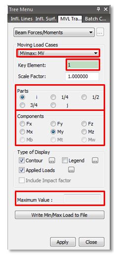
Similarly, to view the maximum sagging moment, select
the MV min Load case.
An image of the vehicle position could be saved for the purpose of Dynamic Report Generation and could later be
added to the Analysis Report.
Clicking on ‘Write Min/Max Load to File’ option, generates a .mct file. Running the .mct file using, Tools > MCT command shell, the said vehicle position is added as a static load case to existing static
load cases.
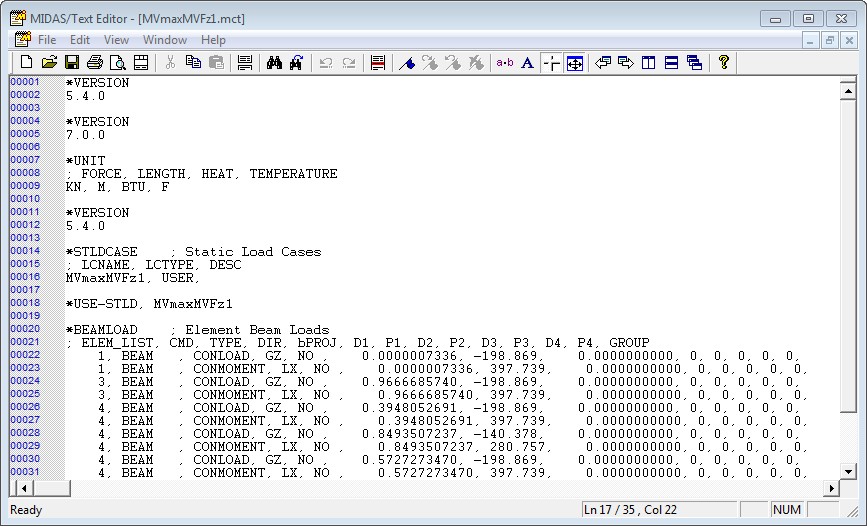
Load Case .mct file to be used in MCT Command Shell
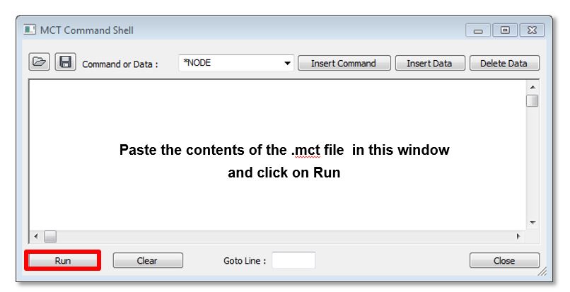
MCT Command Shell window
Since this would be added as a new load case to the existing load case, model has to be
re-analysis. The converted static load could be verified in the tree menu.
Go to Results > Moving Tracer > ‘Beam Forces/Moments…’ or ‘Plate Forces/Moments…’
Midas Civil directly provides the envelop of maximum hogging and sagging bending moments for each element. However, at times it becomes necessary to investigate the vehicle position causing the worst bending moment.
Depending upon the Line Lane or Surface Lane assignment, Beam Forces/Moments or Plate Forces/Moments respectively should be selected to view the results
1. Select MV max load case for max hogging moment.
2. Click on the key element to input the element number
3. Location on the key element i.e ( i, ¼,… implying whether at element’s ith end or quarter length of the element etc.
4. Required Force/Moment components.
5. The value is displayed in a dedicated box besides
‘Maximum Value’
Similarly, to view the maximum sagging moment, select
the MV min Load case.
An image of the vehicle position could be saved for the purpose of Dynamic Report Generation and could later be
added to the Analysis Report.
Clicking on ‘Write Min/Max Load to File’ option, generates a .mct file. Running the .mct file using, Tools > MCT command shell, the said vehicle position is added as a static load case to existing static
load cases.
Load Case .mct file to be used in MCT Command Shell
MCT Command Shell window
Since this would be added as a new load case to the existing load case, model has to be
re-analysis. The converted static load could be verified in the tree menu.
2016_FAQ_Vol.1_image (1)[1].jpg

2016_FAQ_Vol.1_image (1)[1].jpg
2016_FAQ_Vol.1_image (1)[2].jpg

2016_FAQ_Vol.1_image (1)[2].jpg
2016_FAQ_Vol.1_image (102).jpg

2016_FAQ_Vol.1_image (102).jpg
Vol.1_52_How to obtain vehicle position causing Max._Min. Force or moment on an element.pdf
Vol.1_52_How to obtain vehicle position causing Max._Min. Force or moment on an element.pdf
 Get help for this page
 Jitbit HelpDesk