

[BOUNDARY] How to model bearings? How to rotate bearings in case of curved bridge?
Elastic Links are used to model bearings connecting the bridge
substructure and superstructure.
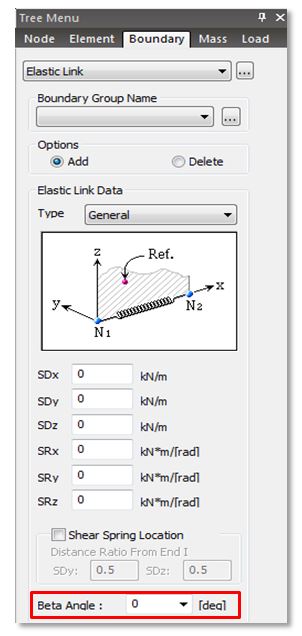
From Main Menu select Boundary > Link > Elastic Link
Enter the Displacement stiffness (SDx, SDy, SDz) and Rotational stiffness (RDx, RDy,
RDz) for the elastic link to simulate the bridge bearings.
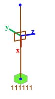
The image below on right, shows the elastic link local axis direction, positive x axis being in the connecting direction of the two nodes. It is important to note that the displacement and rotational stiffness are assigned along elastic link
local axis direction.
In case the exact stiffness values are not known, arbitrary stiffness values could be assigned to reach a better approximation of result.
For example, neoprene bearings have high axial stiffness (SDx) and hence could be high, say 107 kN/m and
lower shear stiffness (SDy and SDz), say 100 kN/m. For guided bearings (like POT-PTFE bearing), high values for SDy and/or SDz could be
assigned to simulate high lateral bearing stiffness.
Bearings for Curved Bridges
In case of curved bridges, beta angle should be assigned to these elastic links to change the bearing local axis orientation, either
aligned tangentially to the curve of in line with the fixed support, as depicted in the image below.
Beta angles could be assigned while creating the elastic link or later from the tables.
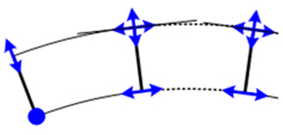
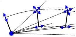
Tangential to curve In line with Fix Support
substructure and superstructure.
From Main Menu select Boundary > Link > Elastic Link
Enter the Displacement stiffness (SDx, SDy, SDz) and Rotational stiffness (RDx, RDy,
RDz) for the elastic link to simulate the bridge bearings.
The image below on right, shows the elastic link local axis direction, positive x axis being in the connecting direction of the two nodes. It is important to note that the displacement and rotational stiffness are assigned along elastic link
local axis direction.
In case the exact stiffness values are not known, arbitrary stiffness values could be assigned to reach a better approximation of result.
For example, neoprene bearings have high axial stiffness (SDx) and hence could be high, say 107 kN/m and
lower shear stiffness (SDy and SDz), say 100 kN/m. For guided bearings (like POT-PTFE bearing), high values for SDy and/or SDz could be
assigned to simulate high lateral bearing stiffness.
Bearings for Curved Bridges
In case of curved bridges, beta angle should be assigned to these elastic links to change the bearing local axis orientation, either
aligned tangentially to the curve of in line with the fixed support, as depicted in the image below.
Beta angles could be assigned while creating the elastic link or later from the tables.
Tangential to curve In line with Fix Support
2016_FAQ_Vol.1_image (1).jpg

2016_FAQ_Vol.1_image (1).jpg
2016_FAQ_Vol.1_image (1)[1].jpg

2016_FAQ_Vol.1_image (1)[1].jpg
2016_FAQ_Vol.1_image (10).png

2016_FAQ_Vol.1_image (10).png
2016_FAQ_Vol.1_image (26).jpg

2016_FAQ_Vol.1_image (26).jpg
Vol.1_15_How to model bearings_ How to rotate bearings in case of curved bridge_.pdf
Vol.1_15_How to model bearings_ How to rotate bearings in case of curved bridge_.pdf
 Get help for this page
 Jitbit HelpDesk